Tuesday, May 31, 2022

GODIAG OBD2 Jumper cooperates with PCMtuner MPM Tool to read ECU

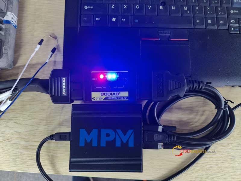
 This is reading 2007 Cadillac E67 GM ECU with MPM Chip Tuning Tool + GODIAG GT105 Adapter to do power setting and DTCs blocking. ECU module should be removed from vehicle. By connecting to GT105, we can check whether the ECU is working properly.

Tools:

Cadillac ECU Module

MPM ECU-TCU Tool

GODIAG GT105

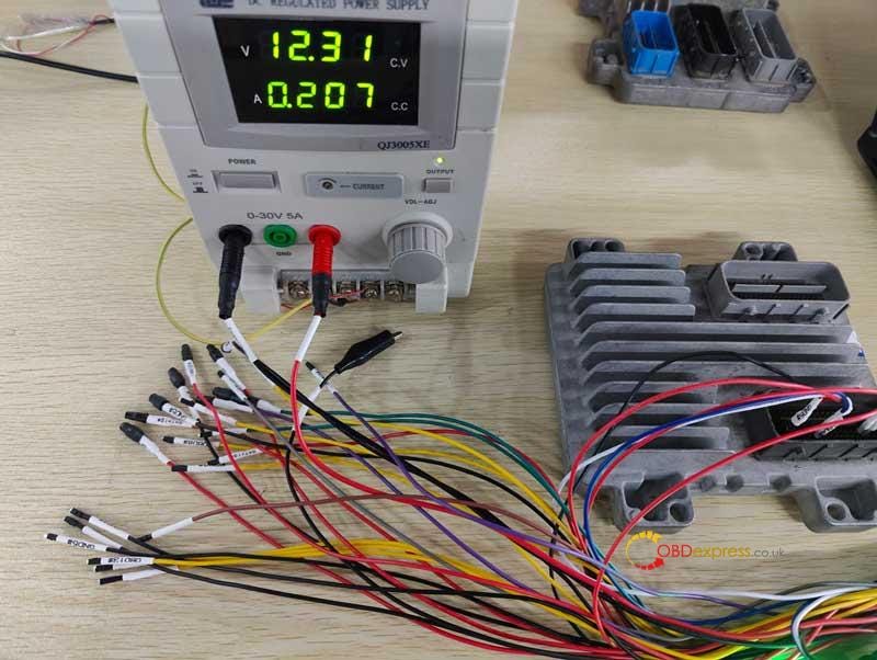
Programming Power Supply

GODIAG Full Protocol OBD2 Jumper(Supports use alone or MPPS/KESS V2, etc.)

GODIAG OBD2 Jumper cooperates with PCMtuner MPM Tool to read ECU

GODIAG OBD2 Jumper cooperates with PCMtuner MPM Tool to read ECU

GODIAG OBD2 Jumper cooperates with PCMtuner MPM Tool to read ECU

GODIAG OBD2 Jumper cooperates with PCMtuner MPM Tool to read ECU

Connection

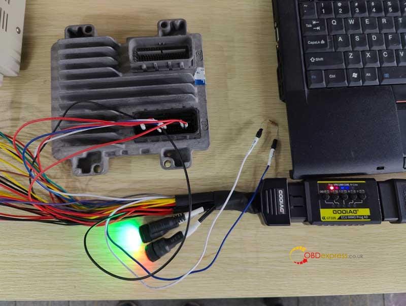
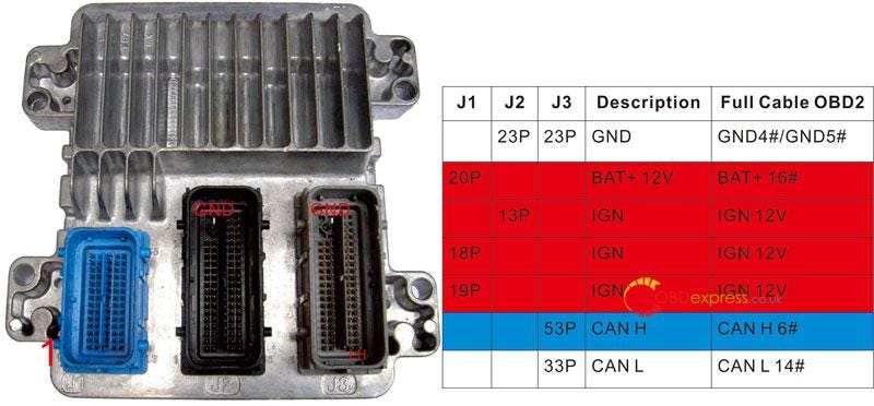
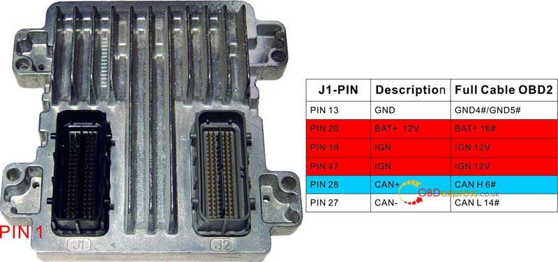
  • Connect ECU & GT105 via jumper cables, which can work as Tricore cables to read ECU.
  • Connect MPM to computer & GT105.
  • Turn ignition on. GT105 blue lights will flash once the ECU starts data transmission. That means the ECU can communicate normally.
    1. GODIAG OBD2 Jumper cooperates with PCMtuner MPM Tool to read ECU

      GODIAG OBD2 Jumper cooperates with PCMtuner MPM Tool to read ECU

      Read ECU

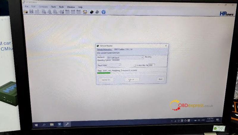
      Open MPM HPtuners software to identify VIN,

      Select ECU model: E67 GM Gen4 >> Read entire >> Read

      MPM will starts reading automatically… just wait 2 minutes.

      Meanwhile, you can see the GT105 blue lights keep flashing during whole process.

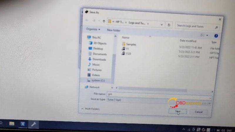
      Save file after reading.

      Done.

      GODIAG OBD2 Jumper cooperates with PCMtuner MPM Tool to read ECU

      GODIAG OBD2 Jumper cooperates with PCMtuner MPM Tool to read ECU

      Quite easy, simple operation as PCMTuner. With above tools, for car owners who need to adjust ECU can send for MPM processing. Once done, just reinstall ECU back to car.

      Read also:

      Free download MPM ECU-TCU Chip Tuning Tool Software 4.10.4

      How to solve PCMTuner Bench mode not work? (attached wiring diagram)

      Here share the solution to resolve PCMTuner cannot work on bench mode, and also provide the PCMTuner Module 58/61/71 wiring diagrams for users to quickly view the wiring diagram offline without network, and for some users who only have our PCMTuner Smart Dongle as well.

      PART 1: PCMTuner Bench Not Working Solution

      The possible causes:

    2. The cable is not connected correctly between PCMTuner Magic Car Tool and ECU.
    3. Select an incorrect protocol (ECU model) in pcmflash software for ECU reading and writing.
    4. Using other power supply not PCMTuner cause the burning of the device transistor.
      1. The corresponding solutions:

        1. Make sure the device and ECU connection via bench cable is proper.

        2. Select the correct protocol (ECU model) in pcmflash software when reading or writing ECU.

        3. Do not plug in a separate 12V when you use OBD for power supply, otherwise, it will cause the device transistor or step-down chip to burn.
        MUST USE PCMtuner professional power supply!

        If you use your own lab power and voltage regulator, you cannot know how device power works, and just adjust the voltage to 13.5 or whatever you think will cause the whole triode to burn out.

        If the PCMTuner transistors are burnt, you need to replace transistors.

        The transistors need to be replaced:

        • N1 transistor: with MMUN2113LT1G
        • N2, N3 transistor: with MMUN2211LT1G

        Check the corresponding positions marked below:
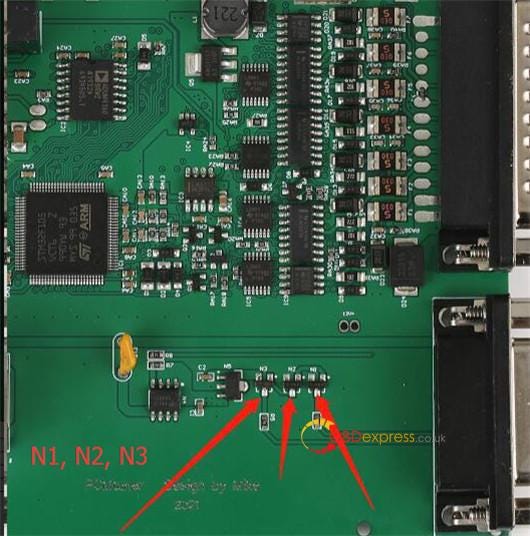
        PCMTuner Bench Not Working Solution (Module 58 61 71 wiring diagram attached)

        • Q3, Q9, Q10, Q11 transistor: with MMBT2222A-7-F

        Check the corresponding positions marked below:
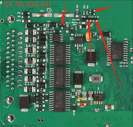
        PCMTuner Bench Not Working Solution (Module 58 61 71 wiring diagram attached)

        PART 2: PCMTuner Module 58/61/71 Wiring Diagram

        Free download PCMTuner 58, 61, 71 protocols instruction

        PCMTuner Module 58

        Temic DSG/CVT

        Function

        DQ200MQB/G2 (0CW)

        DQ250MQB (0D9)

        Reading, writing, checksum correction

        VL381/DL382 (0AW/0CK)

        DL501/G2 (0B5)

        DQ200 (0AM)

        DQ250E/F (02E)

        VL300/V30 (01J/0AN)

        Writing, checksum correction

        DQ200/MQB/G2 Boot (EEPROM)

        DQ250E/F/MQB Boot (EEPROM)

        DL501/G2 Boot (EEPROM)

        VL381 Boot (EEPROM)

        DL382 Boot (EEPROM)

        Honda UDCT Boot (Continental TC1782/EEPROM)

        Reading, writing

        DQ200/MQB/G2 Boot (MICRO)

        DQ250E/F/MQB Boot (MICRO)

        VL381 Boot (MICRO)

        DL501/G2 Boot (MICRO)

        DQ500 (0BH/0BT)

        VL300/V30 BSL (FLASH)

        VL300/V30 BSL (EEPROM)

        DQ250C (02E)

        DL382 Boot (MICRO)

        Honda UDCT Boot (Continental TC1782/MICRO)

        Reading, writing, checksum correction.

        VAG DQ200 (0AM, 0CW) TCU
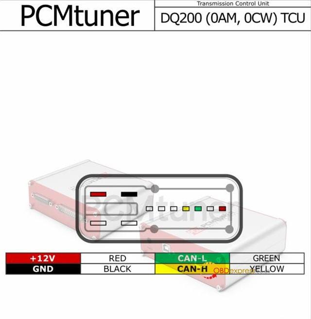
        PCMTuner Bench Not Working Solution (Module 58 61 71 wiring diagram attached)

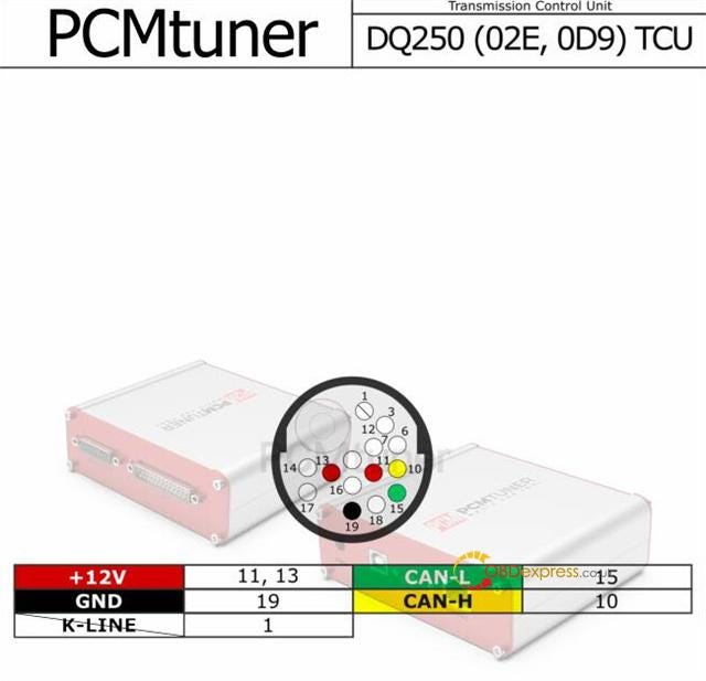
        VAG DQ250 (02E, 0D9) TCU

        PCMTuner Bench Not Working Solution (Module 58 61 71 wiring diagram attached)

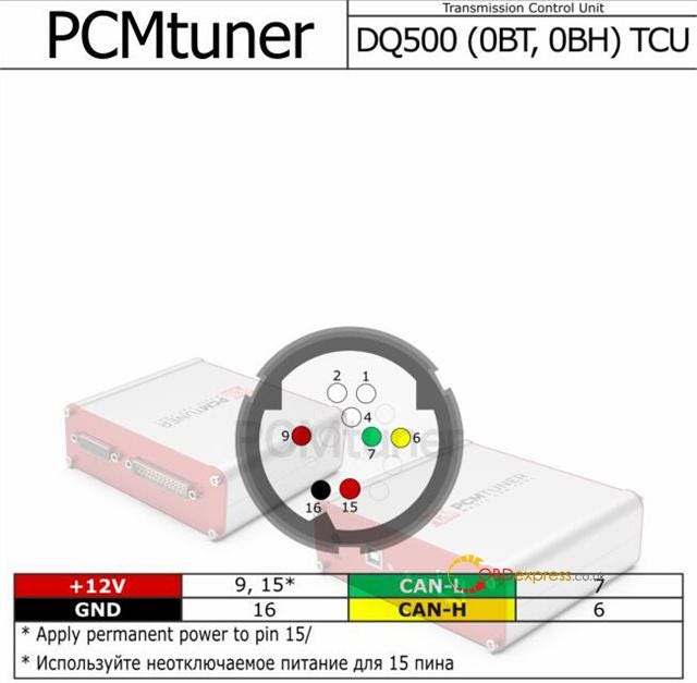
        VAG DQ500 (0BT, 0BH) TCU

        PCMTuner Bench Not Working Solution (Module 58 61 71 wiring diagram attached)

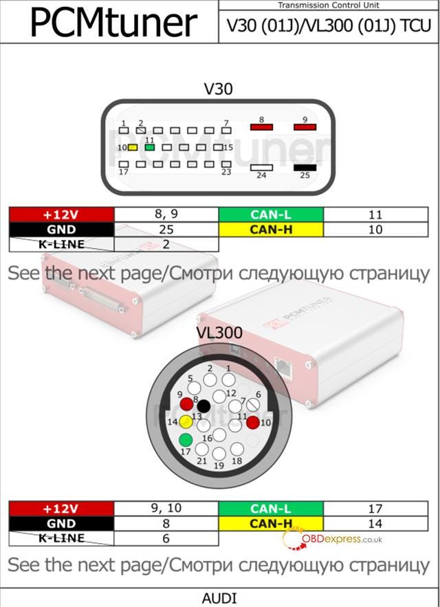
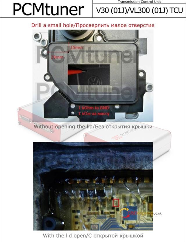
        Audi V30 (01J)/VL300 (01J) TCU

        PCMTuner Bench Not Working Solution (Module 58 61 71 wiring diagram attached)PCMTuner Bench Not Working Solution (Module 58 61 71 wiring diagram attached)

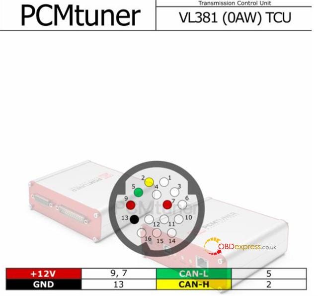
        Audi VL381 (0AW) TCU

        PCMTuner Bench Not Working Solution (Module 58 61 71 wiring diagram attached)

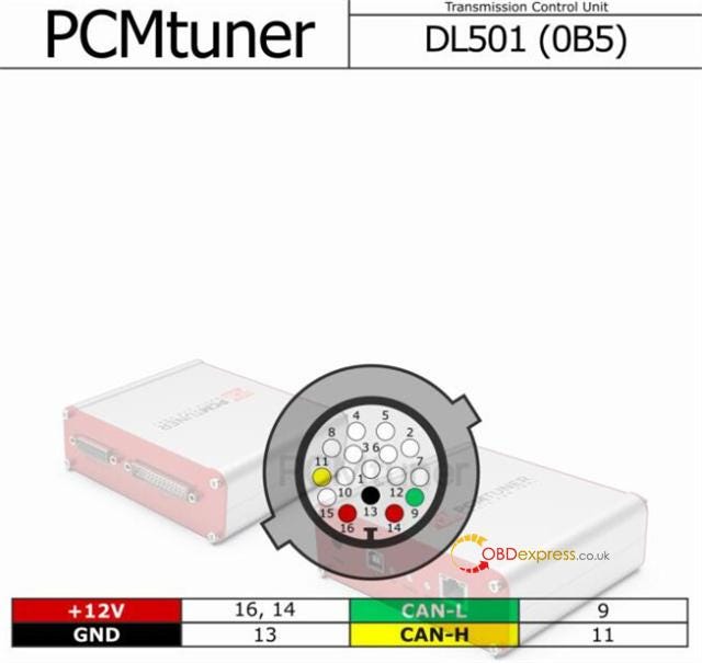
        Audi DL501 (0B5) TCU

        PCMTuner Bench Not Working Solution (Module 58 61 71 wiring diagram attached)

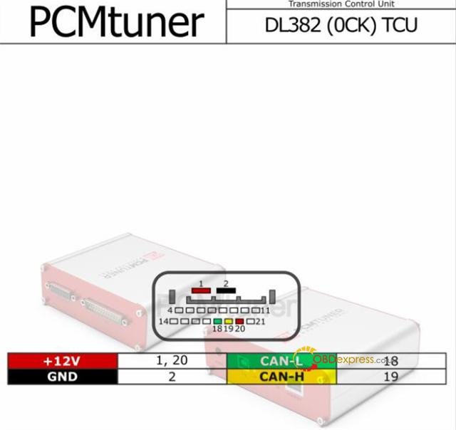
        Audi DL382 (0CK) TCU

        PCMTuner Bench Not Working Solution (Module 58 61 71 wiring diagram attached)

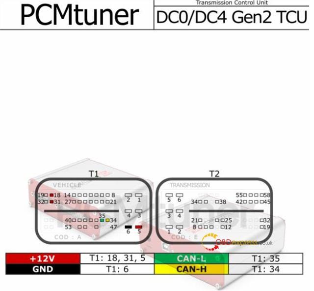
        Renault DC0/DC4 Gen2 TCU

        PCMTuner Bench Not Working Solution (Module 58 61 71 wiring diagram attached)

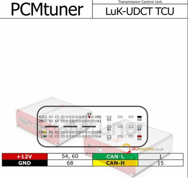
        Honda LuK-UDCT TCU

        PCMTuner Bench Not Working Solution (Module 58 61 71 wiring diagram attached)

        PCMTuner Module 61

        Kia Hyundai CPGDSH/CPEGD

        1.6L (CPGDSH2.24.1/CPEGD2.20.1/UDS

        Reading, writing, checksum correction.

        1.4T, 1.6L (CPEGD2.20.3/CPEGD2.20.4/UDS) — requires a direct connection to the ECU

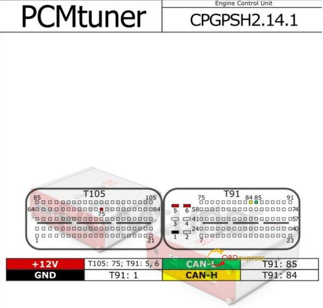
        1.0L, 1.2L (CPEGP2.10.1/CPGPSH2.14.1/UDS)

        Reading, writing, checksum correction, unlocking

        CPEGD2.20.x
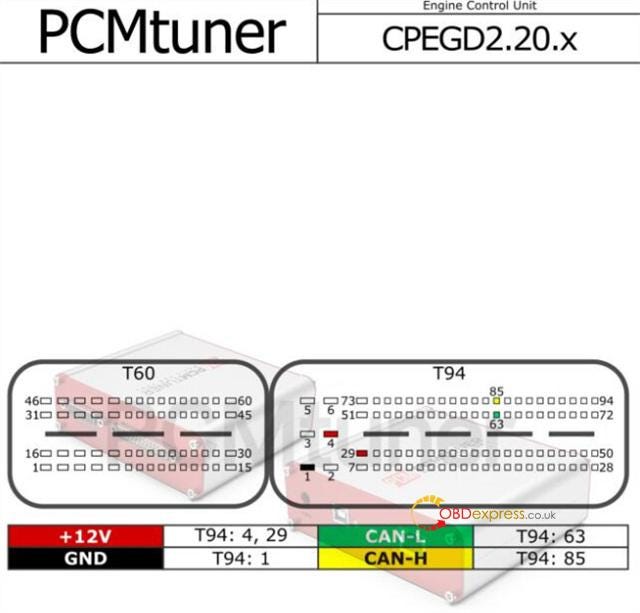
        PCMTuner Bench Not Working Solution (Module 58 61 71 wiring diagram attached)

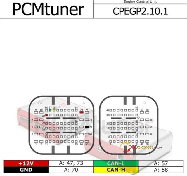
        CPEGP 2.10.1

        PCMTuner Bench Not Working Solution (Module 58 61 71 wiring diagram attached)

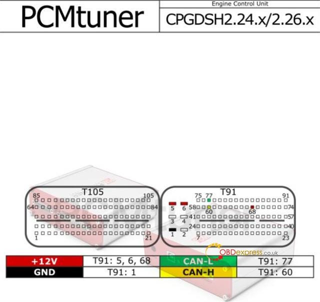
        CPGDSH2.24.x/2.26.x

        PCMTuner Bench Not Working Solution (Module 58 61 71 wiring diagram attached)

        CPGPSH2.14.1

        PCMTuner Bench Not Working Solution (Module 58 61 71 wiring diagram attached)

        PCMTuner module 71

        PCMTuner Bosch MEDC17 Bootloader

        (direct connection to the ECU connector, Scanmatik 2 Pro, a connection cable, and a power supply are required)

        MEDC17 (TC1762/1766/1792/1796) FLASH

        MEDC17 (TC1724/1728/1767/1782/1784/1797) FLASH

        MEDC17 (TC1791/1793) FLASH

        Reading, writing, checksum correction.

        MEDC17 (TC1762/1766/1792/1796) EEPROM

        MEDC17 (TC1724/1728/1767/1782/1784/1797) EEPROM

        MEDC17 (TC1791/1793) EEPROM

        Reading, writing.

        MEDC17 BSL PASSWORD

        Reading.

        Module 71 includes lots of ECUs and pinout diagrams.

        The module 71 wiring diagrams are available in the download link above.

        www.obdexpress.co.uk
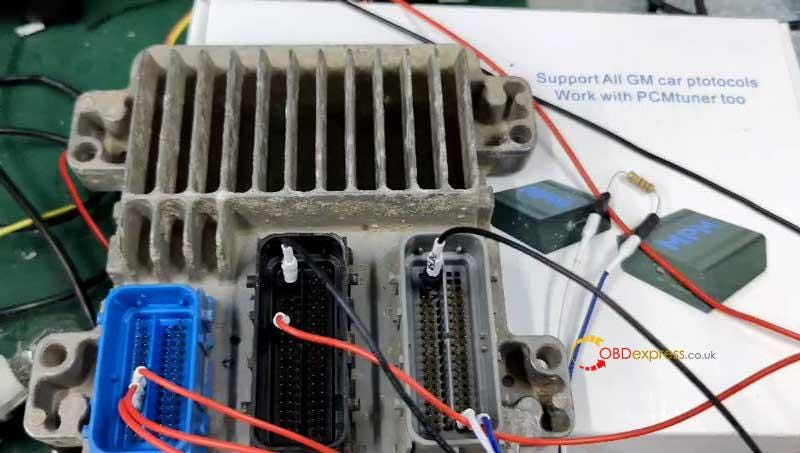
        Solution: PCMTuner Device No Response, Cannot Be Found etc, Problem

         Good to know:

        PCMTuner software has updated to V1.2.6 now.

        PCMflash software still be V1.20, don't update it to other higher version.

        PCMTuner V1.2.6 update info:

        • MPM option is operational
        • Scanner option is operational
        • Metrotech button add and will come soon

        PCMtuner common problem and solution:

        1. Problem: Cannot connect to computer. There is no response when connecting to computer.

        Solution: The reason is that the power supply of pcmtuner is divided into USB communication power supply and PCB host power supply. Many users often plug USB into the system separately and no PCB power supply leads to no reaction of the device.

        2.Problem: Sometimes PCMTuner software prompts the device cannot be found when identifying and reading data.

        Solution: In this case, just plug and unplug the adapter power supply.

        3. Problem: PCMTuner software shows not active.

        Solution: After you register, just wait for 24 hours, and the factory will activate for you automatically. No need to offer an email to the seller to activate now.
        If over 24 hours, still not activated, can ask your seller to check for you.
        NOTE: if you change the computer to install, still need to ask YOUR SELLER to re-activate for you
        Remember one tool, one email, one computer!

        4. Problem: The PCMTuner Smart Dongle or PCMTuner device cannot be found.

        Solution: Plug in the PCMTUNER ECU Programmer to supply power, and connect USB and Smart Dongle as well.

        5. Problem: Where to log in account?

        Solution:

        • vz-performance.com: User Name is your registered Email and Password is the PCMtuner Serial Number.

        This account will be used for tuner support. It has VR file and many damaos there.

        • tuner-box.com: User Name is your registered Email and Password is the PCMtuner Serial Number.

        This account will be used for checking the support list of PCMtuner, creating ticket support tool user, etc.

        6. Problem: PCMTuner Dongle gets heat.

        Solution: There is a chip inside of the dongle, it is set as a safety factor, and it is the reason for the dongle getting hot.
        If your dongle is overheating, please contact our customer service to help you remove it.
        DON'T DO IT yourself if you did not contact the engineer, or it will lock the dongle.
        Besides, we have returned our stock back to the factory for testing, New stock will come after 5 days, and there is no problem with the dongle for the new stock.

        7. Problem: Will the device burn if use another power supply, not PCMTuner?

        Solution: Don't use your power supply, or it will burn triode easily.
        If you use OBD for power supply, please do not plug in a separate 12V, otherwise, it will cause the device transistor or step-down chip to burn.
        MUST USE PCMtuner professional power supply!
        If you use your own lab power and voltage regulator.
        You don't know how device power works.
        Just adjust the voltage to 13.5 or whatever you think will cause the whole triode to burn out.

        Kindly notice:

        PCMTuner Magic Car Tool supports OBD, bench, and boot modes.

        Users often choose other protocols after the connection diagram is completed. If the cover of the connection diagram is not opened, please choose protocol 71, which corresponds to the MCU of your ECU. The MCU is indicated inside the PCMTUNer wiring diagram.

        Toyota, Volkswagen, Audi and Honda can select virtual files. To select virtual files, ID must be identified first, and then the corresponding ID number should be retrieved, or sw software number, or part number, corresponding to the downloaded file.

        www.obdexpress.co.uk
        Monday, May 9, 2022

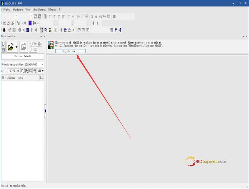
        How Activate PCMtuner and get WinOLS Damaso file?

        I bought a PCMtuner ecu programmer. I have already downloaded and installed WinOLS from support.vz-performance.com. When I opened it to use, the software required me to activate with user name and password. How to activate?

        obdexpress.co.uk technician replied:
        Just click 'Register now…' in the WinOLS software to register by yourself, no need to be activated by factory.

        activate PCMtuner to get free Winols Damaso file

        But you need to pay for the registration. After that, you can use WinOLS damaso file, WinOLS damaos and MAP package for free. Just click search, then type what you want, there will have. If there is no file you want, create ticket to contact factory.

        For any problems, please feel free to contact our customer service(obdexpress.co.uk).

        PCMtuner ECU Services usage process description

         Attention please DO NOT upgrade PCMflash 1.20 version while updating V1.25 PCMTUNER. Otherwise, PCMtuner Dongle will be unable to identify. Here we provide PCMflash 1.20 software free download link for misoperation.

        Free download PCMflash 1.20 app

        System: Win10

        Size: 11.8MB

      2. Uninstall PCMflash new version only;
      3. Re-install PCMflash 1.20.
        1. How to use PCMtuner to do ECU Services?

          This is an operation guide on using PCMtuner to do ECU services, including power adjustment, immo off, dpf/egr remove, dtc shielding, etc.

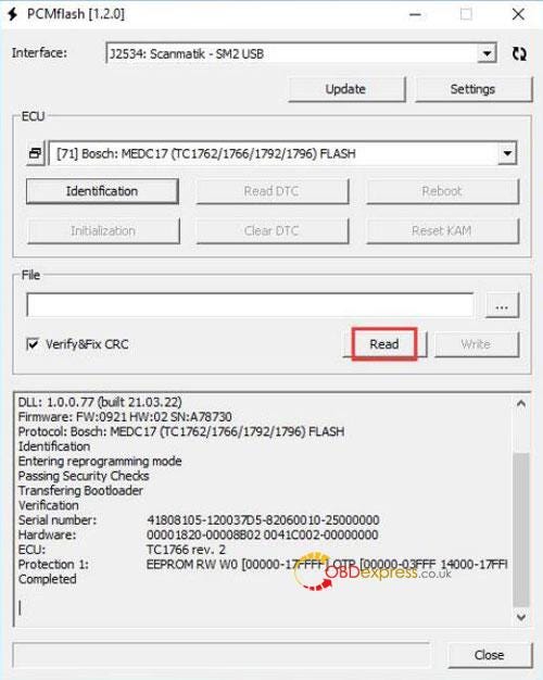
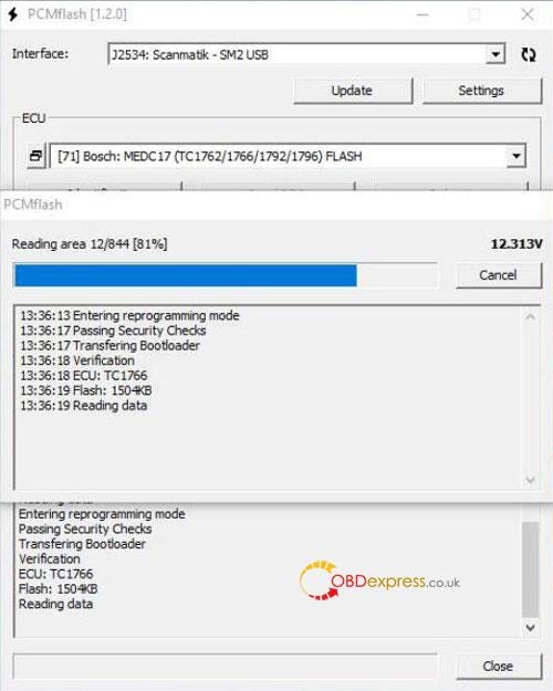
          Step1. Read flash data of the ECU via Pcmtuner.

          Note: For only buying PCMtuner Dongle users, need to use other device to read flash data. Eg. Tactrix Openport 2.0, Scanmatik 2 PRO,etc.

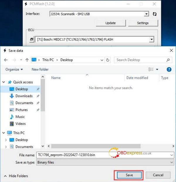
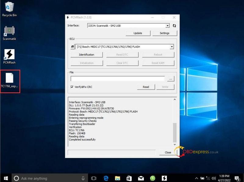
          Click “Read >> Save”

          PCMtuner ECU Services usage process description

          PCMtuner ECU Services usage process description

          PCMtuner ECU Services usage process description

          Step2. Send info & requirements to factory for revision.

          Information: ECU flash data + car model + ECU model

          Requirements:

        2. Verifythe payment has been finished.
        3. Explains ECU services needs.(eg.power transfer, immo off, dpf/egr remove, dtc shielding, etc.)
          1. PCMtuner ECU Services usage process description

            Step3. Write processed flash data back to ECU via PCMtuner.

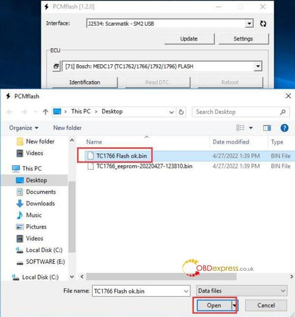
            Factory will send back processed flash data, just write back to ECU.

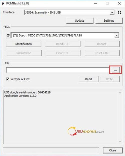
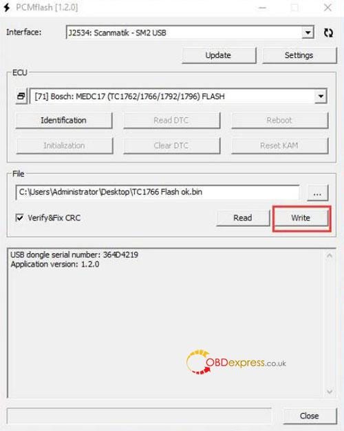
            Load file >> Write

            PCMtuner ECU Services usage process description

            PCMtuner ECU Services usage process description

            PCMtuner ECU Services usage process description

            Technical support

            www.obdexpress.co.uk